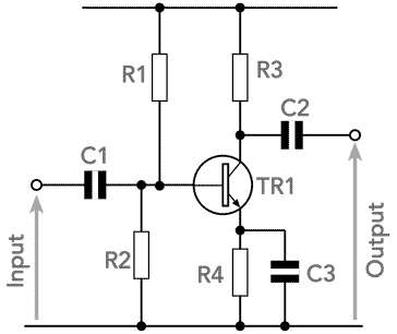


When supply is given to the circuit, the voltage divider circuit output provide enough voltage to bias the transistor.

You can change the resistor value but the base input voltage should not exceed the range. A transistor’s base terminal voltage required to turn ON the transistor ranges from 0.7 (min) to 5V (max). Hence, the output of the voltage divider circuit is used for proper biasing to turn ON the transistor. In the above circuit diagram, we have made a voltage divider circuit using resistor R1 and R2 of 4.7k and 1.5k respectively. Simple Transistor Amplifier Circuit Diagram The output signal phase shift is 180⁰, hence the output and input are inverse to each other.Ĭomponents Required for a Transistor Amplifier Circuit This configuration is most used configuration among all the three, as it has average input and output impedance value. The current gain (Beta) is defined by the ratio of collector current and base current in this configuration. In this configuration, the sum of collector and base current is equal to the emitter current. Here, the input parameters are V BE and I B and output parameters are V CE and I C. This configuration is an inverting amplifier circuit. Input is supplied to the base terminal and the emitter is common for the Input and Output. In the CE (Common-Emitter) Configuration, we get output from the collector terminal. For, learning about other two configuration, types of transistors and their working follow the linked article. Here, we are explaining Common-Emitter configuration, as it is the most used and popular configuration.

Transistors are the semiconductor devices used for switching or amplifying electrical signals.


 0 kommentar(er)
